

MENJUAL KOMPONEN RADIO : Transistor Mosfet, Varco, trimer, IF Biru dll
RA 40
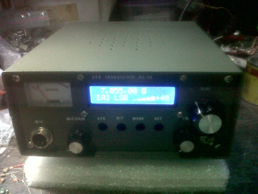
SSB TRANSCEIVER 40 M BAND
Wednesday, October 6, 2010
Thursday, September 30, 2010


Tuesday, August 3, 2010

Thursday, July 29, 2010
LM 386 74 dB

LM386 is very popular IC also in Japan. It is used in Radio receiver. The power of it (500mW) is enough for the personal use. But sometimes, the gain of it (40dB) is not enough. Especially the direct conversion receiver depend on all of its gain on the audio amplifier. And therefore, we must stay sometimes the pre-amplifier before LM386. I will show you the way to get the 74dB only with LM386. Please watch the circuit ! Rf is the feedback control resister. By chanbeing the Rf you can tune the gain of this circuit as follows.
| Rf (ohm) | gain |
| feedback
| dB |
| 3.3 | 74 |
| 10 | 70 |
| 33 | 54 |
| 105 | 44 |
| 820 | 34 |
Dear Sunamura-san, I like to read your web-site very much, and I repeated some of your constructions. I especially like your LM386 70 dB AF amplifier which I called =B3the Sunamura amplifier=B2 in our national Ham Magazine. Now, I have some news for you. The other day I found in our national ham magazine a new type of a rock stable VFO. They did not mention the first inventor, but I will try to find out who it was. It is a =8CColumbus= =B9 egg=B9 and it can substitute syntesizers. It uses a CERAMIC RESONATOR, and the frequency can be spread for about 100 kHz. I attach the electric diagram. The chief part s are the Ceramic Resonator CR and the variable capacitor C1. I used a standard CR for 3.579 kHz which is used as a clock in American digital devices. After a short warm-up, when you turn the capacitor C1 you can change the frequency for about 150 kHz - from 3440 to 3620 kHz. To cover the CW segnment of the 80 mteres band a variable capacitor of 140 pf is enough. And the frequency is rock stable. The capacitors C2 and C3 must have a capacity similar to the own capacity of the CR. In my case it was 600 pF. I also tried the ceramic filter for 10,7 MHz with three pins, but then I had to use 50 pF for C2 and C3, because that was the capacity of the filter. I used only two pins: the middle one and a side one - The frequency was between 10,9 and 11 MHz and the stability was very good. I also tried a 5,5 MHz filter, but it did not work well - it gave a frequency of 17 MHz with only 10 kHz of spread. I am sure that you will make use of this oscilator - with your tehcnical ingenuity. When I get some new CRs, I will make some more experiments. Meanwhile, I remain with best wishes, Bozidar Pasaric, 9A2HL, City of Rijeka, Croatia, Europe My E-mail: bpasaric@mac.com
Created by JF1OZL
Tuesday, July 20, 2010
One Transistor DSB Transmiter
One transistor TX (50MHz DSB)...1trtxph.gif
I challenged to make very simple transmitter. It is constructed with only one transistor. It makes DSB signal. It can make QSO with normal SSB station. ***
See fig 1! Carbon microphone modulates 50MHz CW signal. It produces a double sideband signal. It pass through the 50MHz band pass filter. It is radiated by the antenna. ***
See fig 2! Modulator is constructed by diode single balanced mixer. ***
See fig 3! This machine is transmitter. Therefore I must use another transceiver in order to receive the report from my QSO friends. ***
See the table! With this machine I made four QSO's with friends living 50Km distance from me.
Table1: result of one night local expedition by this transmitter. All QSO was mwde on 18 Dec 1993.
| time(JST) | QTH of contact station | distance(km) | Report receiv | memo |
| 2121 | Kumagayacity | 67 | 41 | Not good signal.But recognized. |
| 2140 | Kawaguchicity | 57 | 34 | Only call sign was copied. |
| 2205 | kazocity | 47 | 45 | He could hear that I say " Carbon mic is used". |
| 2215 | Kakegawacity | 57 | 45 | Small beet was heard. Carbon mic was heard. |
Created By JF1OZL
Friday, February 5, 2010

Wednesday, January 27, 2010
El Silbo
Please click here to download the schematic

This double-sideband (DSB) radiotelephone transmitter is powered entirely by the instantaneous (not stored) energy produced in the operator's voice. The RF output power in my prototype falls within the range of 5 to 15mW. The circuit is essentially a high-level DSB modulator/crystal-controlled RF oscillator.
To date, my best DX QSO with this radio stands at 160km/100 miles (please see the station log below).
Please click here to hear El Silbo on W1TXT's receiver, located near
I'm saying, "CQ CQ AA1TJ Voice Powered Transmitter 5mW." I know it doesn't sound like much, but please bear in mind the signal that you hear was projected 245km by the instantaneous power of my voice. A comment about this recording posted to Bill, N2CQR's, Solder Smoke Blog made me smile.
"The audio samples are eerie; remind me of those audiograms recorded back in the 1860s...you know, the woman singing the French folksong snippet..."
Thank you, Roberto. Oh yes, I know the clip that you're referring to. You can hear it here.
10/26/09; This afternoon I substituted an electret microphone (salvaged from an old telephone) directly driving an LM386 audio frequency amplifier in place of the voice-driven "loudspeaker" (SP1) shown in the above schematic diagram. This produced a peak DSB output power of 100mW (50mW in each sideband). I worked four stations on 75m this evening with this setup. Please click here to hear a recording of my signal made by W1PID (thanks Jim!) at a distance of 109km (the louder signal that you hear at the end is Seabury, AA1MY).
Circuit Operation
Speaking into the permanent magnet loudspeaker, an audio frequency alternating current will appear at the secondary winding of transformer, T1. When the signal on the upper end of this winding turns positive, diode D1 will become reverse-biased (effectively disappearing from the circuit). At the same time diode D2 will become forward-biased, and thus clamp both the collector of Q2 and the lower end of the primary of transformer T2, to ground. The Colpitts crystal oscillator - centered around Q1 - will begin to oscillate (the Colpitts capacitive divider consists of C6 and the active transistor's internal base to emitter capacitance).
When the audio frequency signal reverses polarity, Q1 becomes "clamped-off" and RF oscillation will commence in the Colpitts circuit, now centered around transistor Q2. An identical amplitude, but 180 degree phase-shifted, RF signal will appear on the secondary of transformer T2; as it must to insure proper DSB modulation.

Look Ma...No String!
El Silbo takes its name from Silbo; a whistled language (of sorts) that's used on the isle of La Gomera (Canary Islands) to communicate across wide mountain valleys. The best DX is apparently 2 miles, or just over 3km.
Some History
The idea for a voice-powered radiotelephone transmitter appeared not long after transistors first became widely available (my thanks to Roger, G3XBM, for unearthing this!). I wonder what became of Mr. Bryan's AM radiotelephone transmitter?
Time Magazine (October 17, 1955)
"The Army Signal Corps has developed a radio transmitter that needs no energy except electricity generated by the speaker's voice. The trick would be impossible if the set used vacuum tubes, but all it has is a single transistor, which needs only a faint current. When the speaker's voice makes the microphone vibrate, it generates enough current to operate the transistor and put the voice on the air. The present model, small enough to fit in a telephone mouthpiece, can transmit 600 ft. Later models, says George Bryan, developer of the set, should be good for a full mile.
Next step will be to build a voice-powered receiver. It will store up voice-electricity while the speaker is talking, then use it to pick up the answer while he is listening.
Please click here to view a photograph of George Bryan and his voice powered transmitter which appeared in the December 1955 issue of Popular Science Magazine. You may also click here to download the
El Silbo Logbook
Date Station His/Mine QTH Distance My Power Comments
10/13/09 W1VZR 57/459 Limerick, ME 160km 2.5mW Early ckt; resorted to "mouth CW"
10/22/09 AA1MY 57/33 Bethel, ME 160km 5mW 1st skywave voice-pwr fone QSO!
10/22/09 W1PID 59/54
Links
http://www.physorg.com/pdf147367357.pdf
Home de AA1TJ
Subscribe to:
Posts (Atom)